 Microprocessor
68000
Microprocessor
68000
Microprocessor 68000
ËÁŇÂŕŢ·ŐčˇÓËą´˘ÖéąÁŇĘÓËĂŃşâ»Ăŕ«Ęŕ«ÍĂě˘Í§âÁâµâĂĹŇ«Öč§ăŞéˇŃşŕ¤Ă×čͧáÁ¤ÍÔą·ÍŞ´Ńé§ŕ´ÔÁ
ÁŐ˘ąŇ´ 32 şÔµ, 68000 ăŞéËąčǤÇŇÁ¨Ó´éÇÂÇÔ¸ŐˇŇĂÍéҧµÓáËąč§áşşŕŞÔ§ŕĘéą µčҧ¨ŇˇäÁâ¤Ăâ»Ăŕ«Ęŕ«ÍĂěÂÍ´ąÔÂÁ˘Í§ÍÔąŕ·Ĺ
âÁâµâĂĹŇ 68000 ŕ»çąäÁâ¤Ăâ»Ăŕ«Ęŕ«ÍĂěµéąµĂСŮĹ ´Ö§˘éÍÁŮĹä´é·ŐĹĐ 32 şÔµ ÁŐŞčͧĘ觢éÍÁŮ޹Ҵ
16 şÔµ ¨Ö§ˇÓËą´µÓá˹觢ͧ˹čǤÇŇÁ¨Óä´é 16 ŕÁˇĐäşµě
68000 ·Őč¤ÇŇÁŕĂçÇ
8 ŕÁˇĐŕÎÔõ«ě ăŞéăąŕ¤Ă×čͧáÁ¤ÍÔą·ÍŞËĹŇ ć ĂŘčą ĂÇÁ·Ńé§áÁ¤ÍÔą·ÍŞľĹŃĘ áĹĐáÁ¤ÍÔą·ÍŞŕÍĘÍŐ
ąÍˇ¨ŇˇąŐé 68000 Âѧä»ÍÂŮčăąŕ¤Ă×čͧľÔÁľěáÍ»ŕ»ÔĹŕĹŕ«ÍĂěäĂŕµÍĂě·Ů áĹĐŕ¤Ă×čͧľÔÁľěŕÍŞľŐŕĹŕ«ÍĂěŕ¨çµ·ŘˇĂŘčąÍŐˇ´éÇÂ
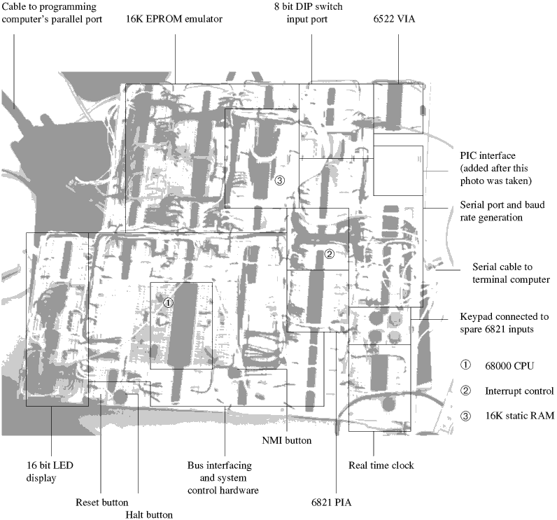
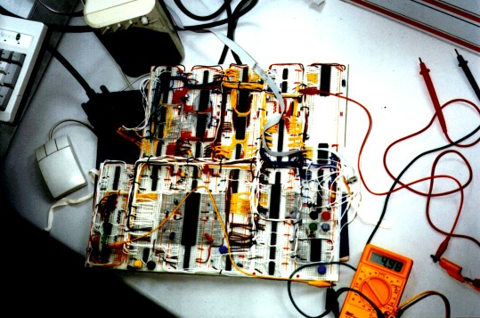
The main features of the 68000 board are:
- 8MHz 68000 processor.
- 16K 100ns static RAM.
- 16K 100ns static RAM with PC parallel port interface, effectively behaving as EPROM erasable and programmable in situ.
- 6821 Peripheral Interface Adapter driving 6818 Real Time Clock and a small keypad.
- 6850 Asynchronous Communications Interface Adapter based serial port with external clock generation, 300 to 307200 bps.
- 6522 Versatile Interface Adapter, driving PIC controlled data link and other external devices.
- 16 bit wide output port, connected to LED display.
- 8 bit wide input
port, connected to DIP switches.
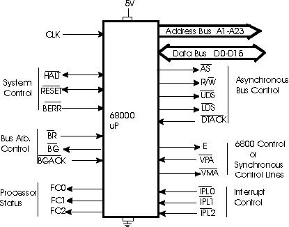
The 68000 has an effective 24 bit address bus, but an actual 23 bit address bus (A1-A23). It uses two control lines to decode A0: UDS and LDS.
Data
Bus:
The 68000 has a 16 bit Data Bus (D0-D15).
Control
Bus:
The 68000 has many control lines, as shown
in the diagram
Asynchronous Control Lines
The Asynchronous Control Lines are shown below. They are:
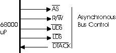
Read/Write - R/W
Upper Data Strobe - UDS
Lower Data Strobe - LDS
& Data Transfer Acknowledge - DTACK
The 68000 uses these control lines when transferring data between itself and 68xxx peripherals. The sequence of events for a memory read is as follows :
- The 68000 places an address on the Address Bus.
- The R/W should already be high (default state)
- The 68000 pulls AS low to indicate that there is a valid address on the Address Bus
- The 68000 will pull
UDS and/or LDS low depending on the data size and the
address being read. - The decoding circuits
and memory ICs then go into action. When memory has been
enabled and the 68000 can complete its cycle, the decoding circuit must pull DTACK low. This input to the 68000 informs the microprocessor that it may now complete the read cycle
Synchronous Control Lines
The Synchronous Control Lines (also known as the 6800 peripheral control lines) are shown to the right. They are:
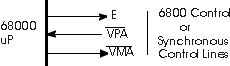
Valid Peripheral Address - VPA
Valid Memory Address - VMA
Officially,
these three control lines are the Synchronous Control Lines; but, a data
transfer to/from a 6800 peripheral cannot take place without AS, UDS,
LDS and the R/W lines. The sequence of events that takes place when the
68000 is transferring data to/from a 6800 peripheral is as follows:
- The 68000 places
the address of the 6800 peripheral (i.e.; the 6821 PIA or 6850
ACIA) on the Address Bus. - The 68000 pulls AS low to indicate a valid address is on the Address Bus.
- The R/W will go into its active state (1 for read, 0 for write).
- UDS and/or LDS will
become active depending on the peripheral device's address
and the size of the data being transferred. - The decoding circuitry
will become active to select and enable the peripheral
device. The decoding circuitry will also pull VPA low to let the microprocessor know that it is trying to access a 6800 peripheral. - The 68000 responds
by synchronizing the E clock with the system clock (the E
clock has a 40% duty cycle, and only one cycle for every ten cycles of the system clock). - When E is synchronized,
the 68000 pulls VMA low to indicate it is ready to
transfer data. VMA should be used as an enable input to the peripheral device. - When E goes high,
the data transfer will take place.
Interrupt
Control Lines
The Interrupt Control Lines are inputs to
the microprocessor and indicate an interrupt level. They can best be summarized
by Table 1.
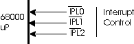
Table 1 - Interrupt Levels
IPL2
IPL1 IPL0
Interrupt Level
1 1 1
0 - No Interrupts
1
1 0
1
1 0
1
2
1 0
0 3
0 1
1
4
0 1
0 5
0 0
1 6
0 0
0 7 - Highest Priority (NMI)
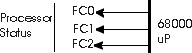
Table 2 - Processor Status
FC2 FC1 FC0
Cycle Type
0
0 0
reserved
0
0 1 user
data
0 1
0 user program
0 1
1 reserved
1 0
0 reserved
1 0
1 supervisor
data
1 1
0 supervisor
program
1 1
1 Interrupt
Acknowledge
Function
Code Outputs
The Function Code Outputs are outputs from
the microprocessor and indicate the microprocessor's status. They can
best be summarized by Table 2.
Bus
Arbitration Control Lines
The Bus Arbitration Control Lines are shown
below. These control lines will allow another microprocessor or a DMA
controller to take over the 68000's Data, Address, and Control busses.
The requesting device, called a Bus Master, requests the use of the 68000's
busses by pulling BR low (Bus Request).
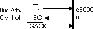
The 68000 will then pull BG (Bus Grant) low to indicate that it will release control of the busses at the completion of the current cycle. When the Bus Master is ready to take control it will assert BGACK (Bus Grant Acknowledge) as long as BG=0, AS=1 (the 68000 is not using the bus), DTACK=1 (no external devices are using the bus), and BGACK=1 (no other Bus Master is trying to use the bus).
The Bus Master can release control of the bus by releasing BR. When it completes its cycle it then releases BGACK, and the 68000 has control of the system busses again.
System
Control Lines
The System Control Lines include BERR (Bus
Error), RESET, and HALT. The BERR signal is used to inform the 68000 that
an error occurred during execution of the
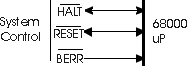
current bus cycle. If the HALT line is NOT low when this happens, the 68000 will execute an exception routine and terminate the current cycle. If HALT is asserted, the 68000 will attempt to rerun the failed cycle.
Both
RESET and HALT are bidirectional signals. Therefore, special care must
be taken in developing the circuits that are connected to these pins.
As inputs and after a power is applied to
the circuit, both RESET and HALT must stay low for 100ms. This is to ensure
that power has stabilized and results in a total processor reset. A total
processor reset will cause the 68000 to load the supervisor stack pointer
from vector 0 (Addresses $000000-$000003) and the program counter from
vector 1 (Addresses $000004-$000007).
Vcc, Ground, and Clock The only lines left are Vcc, Ground, and Clock.
The
Clock has three requirements:
TTL-compatible waveform
50% Duty cycle
10ns rise and fall time (12Mhz versions
and up require 5ns)
The 68000 requires approximately 300mA of
current. This is a little high for one input pin, so there are two Vcc
and two ground pins. Both pins in each set must be connected for proper
operation.